
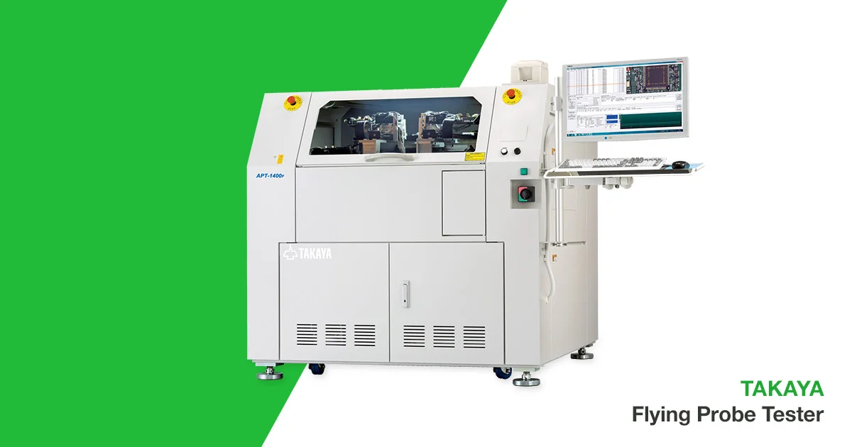
Flying Probe In-Circuit Testing (ICT)
A reputable Electronics Manufacturing Services (EMS) provider or PCB Assembly manufacturer should have extensive knowledge in the industry, coupled with the best technology to manufacture your products. It is crucial to test your PCB Assemblies (PCBAs) in order to avoid costly re-manufacturing fees and wasted materials. In this blog we will discuss available testing equipment for your PCBAs.
There are two types of in-circuit tests (ICT) for PCBAs – the one with fixtures (the bed-of-nails type) and the one without (the flying probes). ICTs are deployed to conduct a range of tests – from a few test points for basic shorts detection to more than tens of thousands of test points for more complex PCBAs.
The flying probe testers became commercially available since the late 1980s. It was first aimed at the simple task of testing of prototypes for circuits that had no good test points. Unlike Bed-of-nails ICT which demands a costly fixture and is not practical for prototypes or small-run PCBAs, flying probe testers are currently widely used in a variety of areas in the electronics manufacturing industry. Moreover, as no conventional bed-of-nails test fixture is required and the creation of initial test program from the PCB design files is quick and easy, the total development time of a flying probe testing routine is drastically reduced to a matter of hours. It has since garnered attention in sophistication and popularity.
Flying Probe Test and Measurement Methods
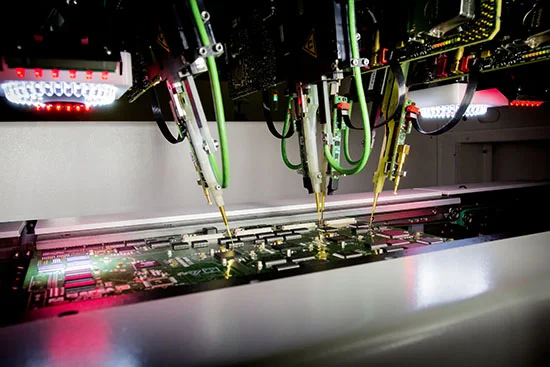
A Flying Prober utilizes a small number of both fixed and movable probes for contacting instead of a bed of nail fixture. The power supply nets are usually contacted using the fixed pins. All the other circuit nodes are contacted in sequence via electro-mechanically controlled pins that can be moved in an x/y direction (contact fingers). Typically, the PC board is placed upside down in the tester, and multiple arms with test probes move across the bottom side of the board, touching down on test points and taking measurements
Flying Probe Testers usually check for shorts, opens, resistance, capacitance, and other basic quantities which will show whether the assembly was correctly configured. It is able to localize defects for easy, cost effective, and quick repair without the help of a specialized technical person and special tools. The precision movement of the test probes (down to 0.3mm fine pitch PCB and smaller with a repeatable accuracy of probe placement of +/-0.05mm) can effectively probe check on lifted legs and dry joints, etc. of an IC package.
Some manufacturers state that their systems have a sufficiently high accuracy to probe on IC types including PLCCs, SOICs, PGAs, SSOPs, QFPs, etc.
The systems can be partially extended to include other test methods such as boundary scans, on-board memory module programming, optical inspection (AOI), functional tests or thermal inspections to allow different solutions to be implemented. A few examples:
• Cameras to test for presence and correct orientation of components
• Photodetectors to test for LED color and intensity
• External timer counter modules to test very high frequencies (over 50 MHz) crystals and oscillators
In-Circuit Test Fields of Application:
In principle, Flying Probe Testers are available for three different fields of application. The testers differ in their features and capabilities.
PCB Test:
To be able to run continuity and isolation tests, these Flying Probers usually operate with a voltage in excess of 100 volts. They are also fitted with around 20 movable probes for highly parallel testing with a high throughput.
PCB Assembly Test:
These systems normally work with 4 movable probes, frequently on both sides of the assembly. In the main the probes are slightly angled so that they can also access the contact surfaces between high components. High fault coverage is also significant here, which means that the systems can be optionally supplemented with other test methods.
Repair Test:
These systems usually operate with just one scan head and one or two probes. An impedance analysis is used to detect faults on the assembly, with the measurement readings being compared against those for a flawless assembly to check for any fault in a certain isolated circuit node.
Flying probe testers are now widely used throughout the electronics manufacturing industry. They provide a much cheaper and more flexible form of in-circuit test. Application of new and innovative design features to increase test speed, board access, reliability, and repeatability, have opened up new possibilities for deployment of flying probe testers.

Learn More About EMS Trends
Top 3 Trends in the Electronics Manufacturing Services (EMS) Industry
Download the free guide to learn more about what benefits customers are currently taking advantage of.